Cisco DSL WICs and Firmwares

Below shows 2 categories in which devices fall into, when connecting over a dsl connection. Either a 800 series router can be used or a DSL WIC card will be used by connection it in another series Cisco router. Note:- There will be other methods of connecting, however my focus is only on these two methods here.

* BT UK ADSL2+ Annex-A using Cisco STM Products [857,867,877,887, HWIC-1-ADSL*] HWIC ADSL modules are based on the ST Micro 20196-PA chipset

* BT UK ADSL2+ Annex-A using Cisco BRCM Products [887-VA and EHWIC-VA-DSL-A] EHWICs support multimode ADSL2/ADSL2+/VDSL technologies based on the Broadcom chipset. The Cisco 880VA Series Multimode VDSL2/ADSL2+ platforms are based on the same Broadcom chipset and support the same DSL modem firmware.

Since IOS 12.4(3)T,  ADSL firmware has been separated into an additional.bin microcode update. The IOS versions do have embedded firmware, however the standalone firmware is preferred for almost all connections.

For 857,867,877,887, HWIC-1-ADSL* (which use ST Micro 20196-PA chipset):

To upgrade the firmware a dsl firmware file needs to be downloaded and renamed as “adsl_alc_20190.bin”. It can then be uploaded to flash (TFTP/SCP shown later in post.)

  1. Download Firmware from – http://software.cisco.com/download/navigator.html       Branch routers>800 Series>(pick a router from the above list i.e. 857)>ADSL Firmware
  2.  Copy Firmware to Flash and ensure the name is “adsl_alc_20190.bin
  3. Reboot the device for firmware to take effect.
  4. “#show dsl interface atm 0” – Should show the firmware source as external rather then embedded!

120913_DSLfirmware_1

The two main fields to be concerned with here are FW Source and FW version (The naming convention of the firmware is also displayed above these).We can verify the firmware has been applied as the FW Source = external
If this read embedded it would still be using the embedded firmware, and there was an error in it using the installed firmware (one thing to check in this scenario is ensuring the file is named adsl_alc_20190.bin)

The below image shows the outcome of a show flash command:

120913_DSLfirmware_2

Here you can verify the naming convention of the file, also notice that although the #show dsl interface atm 0 or  0/0/0 shows the firmware name as different to the file name, (((Investigate issue))))

For 887-VA and EHWIC-VA-DSL-A (supporting multimode ADSL2/ADSL2+/VDSL technologies based on the Broadcom chipset):

  1.  Download firmware from – http://software.cisco.com/download/navigator.html                           Branch routers>800 Series> (select the router i.e Cisco 887VA Integrated Services Router) > Select Very High Bitrate DSL (VDSL) Firmware
  2. Copy the firmware to flash
  3. Configure the router to load from specified location (done under vdsl controller interface) Router(config)#controller vdsl 0
    Router(config-controller)#firmware filename flash:vdsl.bin.bdslfw
    Router(config-controller)#modem UKfeature under controller vdsl 0     (may not tab and must be typed in exact) 
  4. Restart controller by shut/no shutting the controller
  5. Verify by – Router#show controller vdsl 0

120913_DSLfirmware_3

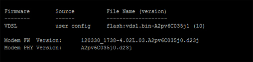
As you can see here the source is user config, this show it is using the firmware we sent to the routers flash and reference under the controller in running config. a show flash command will verify the file name. Also bear in mind, that when using this process, the vdsl controller can be rebooted rather then the entire device.

Useful Links:

During the process of check compatibility with WICs and BT DSLAMs the following sites were ones i found useful and used for reference:


Intermittent DSL and PPP Negotiation diags.

After a ongoing issue with an intermittent dsl connection, and the circuit provider not finding any issues with physical cabling part of the diagnostics i took was to ‘debug ppp negotiation’ and see what i could find.

The output of the negotiation is show below, This was extracted in notepad ++.

080913_PPPtimeouts_1

From the debug we could see that LCP was timing-out. Notice that all the CONFREQ are outgoing messages (O), none are incoming so we are getting no response from the other end. Another a way of showing this is the constant increment on the message ID. we are getting no responses.

Now if attributes were incorrect we would be getting at least a response to tell us they are CONFNAK or CONFREJ but as a result of this we need to look in other areas which could also effect LCP, such as:

* VCI/VPI settings ?
* AAL5MUX or AAL5SNAP ?
* PPPoA or PPPoE ?

CommandS which can verify this are ‘show run’ and ‘show atm pvc’

080913_PPPtimeouts_2

After a bit of reading i found out that the preffered encapsulation for this circuit was AAL5MUX (this will not always be the case). The CCE device used to configure teh connection was defaulting to AAL5SNAP. This had to then be manually changed.

To manually change the encapsulation i typed the following commands.

 (config)#interface atm 0/0/0
 (config-if)#pvc 0/38
 (config-if-atm-vc)#encapsulation aal5mux ppp dialer

After changing this and then shutting down the correct interfaces. The connection came back up and remained stable.

PPP Negotiation Process.

PPP is a Data-link communication protocol In order for it to successfully complete it must go through certain phases. There are 3 main components/steps to PPP and its negotiation process:

Step 1: – LCP (Link establishment Phase).
* This is where parameters are specified for th link o be established, both devices need to agree on authentication type, compression, error detection, multilink and ppp callback. Once the values are agreed it can move onto step 2 or 3.

Step 2: – Authentication (PAP,CHAP or EAP).
* This is an optional phase, but if implemented both devices need to know that the device they are speaking to is who they say they are.

Step 3: – NCP ((Network Control Phase).
* This is the laye 2 to layer 3 transition phase. It provides communication with the IP layer (IPCP). Gives us an IP address we can then communicate with.

One way of verifying step 1 is to run a “sh int atm 0/0/0” (will show the lcp status)

080913_PPP_1

LCP REQsent

(LCP OPEN = LCP successful, LCP CLOSED = Indicates LCP failure, LCP REQsent = both sides could not match parameters i.e mis match of encapsulation)

During the process of PPP negotiation the different packets we will see are:

1. (CONFREQ) > The values that are sent to complete stage (request for information).
2. (CONFREJ) > This will be a return packet if the request is not acceptable or not recognizable,
3. (CONFNAK) > This will be the return packet when the request is recongnizable, however some of the values are not accepted i.e Chap is sent but the other end wants to authenticate with PAP.
4. (CONFACK) > When the router values are accepted, (response to the CONFREQ).

There are also:

1. (TERMREQ) > This is when there is a request for a LCP closure
2. (TERMACK) > This is acceptance of the above.
3. (ECHO REQ/REPLY) >- The PPP keep alives for the connection.

Below shows an overview of the process.

080913_PPP_2

DEBUG PPP Negotiation:

The debug PPP negotiation command is useful because it can not only be used as a vital diagnostic tool, but it also shows the full PPP negotiation process.

Below is an extract from a live debug. You can see the router goes through the 3 phases needed for successful PPP negotiation. Now not all PPP negotiation will go through the exact same process, but it still will be quite similar. (i.e. in a scenario where there is no authentication – as this is an optional phase).

The following images shows how to read a debug output.

080913_PPP_3

Below is the extract of the different phases as seen in a debug output.

080913_PPP_4

Here you can see the LCP start. Notices the stage field changes from PPP (global stage) to LCP. The first CONFREQ is an outgoing request with an ID of 1. However it is followed by an incoming request (ID 124), requests specific LCP attributes (CHAP authentication, MRU, Magic number). The router automatically responds to request which is a CONFACK with its matching attributes. Notice that the response has the same ID number. This way we can match the incoming and corresponding outgoing message.

080913_PPP_5

Once both connections have agreed on LCP details they then need to authenticate against one another. In this output you can see that an Incoming challenge is sent from the remote device, This router has responded to the challenge but full authentication has been unsuccessful. We see this sometimes when authentication has to go through multiple hops. Although the response if a fail here, and the lcp establishment needs to start again (always restarts if there is a fail), the next time the router gets to this stage it will bypass this hop “bras-red4.mqd” (or teh bras will just let it through) and the authentication will go straight to the next stage.

080913_PPP_6

This is the last stage on PPP and it is the NCP stage, so that layer 2 can communicate with layer 3. Notice again the change of stage, which now reads ‘IPCP’. It also shows that LCP stage is complete. The key here is the issuing of the gateway IP (the address the IP needs to speak to, to get its credentials) and teh confirmation of this IP. See ID 87. Once the CONFACK is sent. The router now knows it needs to speak to this IP address to progress.