Cisco AAA Basics

The following post should give you a basic understanding of how to configure AAA and and overall better understanding of what it can do.
First of all AAA stands for Authentication, Authorization and Accounting and it sets – Who can login (Authentication), What can that user do (Authorization), and track the commands that are used (Accounting).


Enabling AAA


TestRouter(config)#aaa new-model

AAA can be configured to use the local database or a remote server like Radius or TACAS+. It is Vital that you create a priv level 15 user on the local database, no matter what method you use. This local user will be a failsafe if anything happens when trying to log in using AAA.


Method Lists


After enabling, we then can create the individual method lists for each AAA function.

A typical method list will look something like this: –  “aaa authentication login default local”

What this means is for aaa authentication use as the default method use the local database! We would then follow this with the ‘aaa authorization…’ and the ‘aaa accounting….’ it all depends on what you want your AAA configuration to achieve.
Below we can see all the options for the authetication method list – here you can see we can create all from the message you see when your presented on the screen, to the amount of attempts.

1_aaa_auth

The most used command at this stage is ‘login’ below shows two examples and what each means will follow.

TestRouter(config)#aaa authentication login AUTHLIST local
 or
TestRouter(config)#aaa authentication login AUTH_LIST group RADIUS_USERS local

The first command would be used if we are using the local database. Here we are saying this authentication method list is called ‘AUTHLIST’ and we will use the local database to verify who can log in.

The second command would be used if we had a remote Radius server. Here we are saying for this authentication method list is called AUTHLIST and we will use the group radius_users. Notice there is a local at the end of this method list, this is used if the group can not be used. It basically means if you can communicate with this group then use the local database (This is why it is impoortant to have atleast one user in the local database as a superadmin)

We also use the same method for authorization method lists, With the authentication method list we have said these users are allowed to connect, but we havent detailed what they can connect to.

The authorization method list also includes many options:

2_aaa_authoriz

 aaa authorization console
 aaa authorization exec EXECLIST group local

Here we enable authorization for console and on the second authorization line, we say this authorization method list is called EXECLIST to check there privileged level of access use the local database.

If we replaced the ‘group local’ with ‘group RADIUS_USERS local’ it was use the group first when reference what commands are allowed and if it couldn’t get a response from this group it would then fall back on the local database.


Using RADIUS/TACAS over the local database.


We referenced the group command ‘group RADIUS_USERS’ in the previous step, but we didn’t explain what it was or how to create it. The group commands allows you to set configuration for a remote Radius or TACAS server. Using the method list above as an example:

TestRouter(config)#aaa authentication login AUTH_LIST group RADIUS_USERS local  —   For authentication use the radius server which is in the group ‘RADIUS_USERS’ if that fails use the local database.
These steps show you how to configure the radius server group and how to get it working:

 aaa group server radius RADIUS_USERS
 server 10.10.10.10 auth-port 1812 acct-port 1813
 server 10.10.10.11 auth-port 1812 acct-port 1813

The above command is telling us that the two radius servers are located at the following addresses use the following ports and group them together as RADIUS_USERS. This command is just for the use with the aaa method list.
There also needs to be a command in the router telling it to connect to the radius server:

radius-server host 10.10.10.10 auth-port 1812 acct-port 1813 key 0000000
radius-server host 10.10.10.11 auth-port 1812 acct-port 1813 key 0000000

And finally there needs to be a command telling the router what ip address to send this request to the radius server from (the radius server may just be expecting communication form a specific ip i.e the loopback).

ip radius source-interface Loopback 0

This will successfully be enough for router to connect to a radius server.


Apply the Method Lists


Now that we have enabled AAA, said who can connect and how they are going to connect, the last stage is to apply the method lists to the correct line e.g. vty lines or console. All we do here is go into the configuration of the line and set the login method…. and the authorization… (the lists we created above).

!
 line con 0
 authorization exec EXECLIST
 logging synchronous
 login authentication AUTH_LIST
 stopbits 1
line aux 0
 authorization exec EXECLIST
 login authentication AUTH_LIST
line vty 0 4
 access-class 10 in
 exec-timeout 15 0
 authorization exec EXECLIST
 login authentication AUTH_LIST
 transport preferred none
 transport input ssh telnet


This should give you enough information for successfully configuring AAA for another perspective on this or more advanced features try the following links below:


An Introduction and something i read which helped me understand AAA: – https://learningnetwork.cisco.com/docs/DOC-7905
Cisco explaining how to configure AAA:- http://www.cisco.com/en/US/tech/tk59/technologies_tech_note09186a0080093c81.shtml

Understanding Role Based CLI

Role based CLI allows you to create a CLI View which restricts access to the CLI command set and interfaces available to a member of that view.

For example: with role based cli a support team can have restricted access to only diagnostics commands (icmp,show commands) a security team can have access to IPS configuration or ZBF commands etc…

There are 4 types of views used in Role Based CLI:

CLI view – The view policy  where you configure the specific roles.
Root view – The mode you have to be in to create a CLI view (priv 15 is’nt enough)
Super view – Allows you to merge multiple CLI views.
Lawful intercept view – Not 100% sure on this one, never really used it.

Below shows how to configure Role based CLI:

Step1 – Getting your bearings right (in the right view)

Firstly enable AAA then we can start getting our bearings, once logged in a ‘show priv’ command will show your current privilege level, follow this by an ‘enable view’ then the password and then ‘show priv’ again which will show you in root view. This is where you can start creating individual views.

TestRouter(config)#AAA new-model
TestRouter#show privilege
 Current privilege level is 15
TestRouter#enable view
 Password:
TestRouter#show priv
 Currently in View Context with view 'root'

1_rbcli_bearings

Note:-  To exit out of this view type ‘en’ and you will be prompted for the enable secret password to get back to priv 15 view.

Step2 – Create a Parser view

After this we need to create the view we want. Ensuring you are in right view (root) you can create a parser view and add the commands you want.

 TestRouter(config)#parser view Remote_Users
 TestRouter(config-view)#secret ****
 TestRouter(config-view)#commands exec include ping
 TestRouter(config-view)#commands exec include traceroute
 TestRouter(config-view)#commands exec include configure terminal
 TestRouter(config-view)#commands exec include all show
 TestRouter(config-view)#commands configure include banner
 TestRouter(config-view)#commands configure include hostname
 TestRouter(config-view)#END

Step3 – Test the view

The best way to test the parser view is to put yourself in that view and see if you can do the commands you need.

TestRouter#enable view Remote_Users
Password:

2_rbcli_testingparser

You can use the ‘?’ to see what commands are available. If more are needed then you can go back to root view and follow the steps in step2 again.

Step4 – Apply the Parser to your users ensure AAA is correct.

So we need to make sure that AAA is using the local database for authorization and that this AAA is applied to the console and vty lines.

The commands for this are:

 aaa authentication login default local
 aaa authorization exec default local
 line console 0
 login authentication default
 exit
 line vty 0 4
 login authentication default
 exit

Note:- If this doesn’t make sense then its advisable to read the Implementing and understanding AAA blog.

Once this is done all you need to do is create a username and password and apply a view.

3_rbcli_username

and that is it. The user joe can now login and have access to the restricted commands.

4_rbcli_login

This link was used extensively when trying to understand role based CLI and its concepts:- http://www.cisco.com/en/US/docs/ios/12_3t/12_3t7/feature/guide/gtclivws.html#wp1067595

How to set up a SSL VPN on a fortigate


Below shows a quick run down of the 8 Key steps needed when creating a SSL VPN on a fortigate.

– Create a user
– Create Address Object
– Enable SSL config
– Create Portal
– Create User Group
– Create Auth Policy
– Create Access Policy
– Create Static Route

 
1. Create User

This will be the user that would to access the SSL VPN. Create a Username and Password and select the Authentication method. The guide will talk you through SSL using the local database.

2. Create an Address Object

At this point the address objects can be created, this will basically be the IP pool used for the SSL VPN. It is best practice to create one global pool and then one pool for each group (using the address range) that will be using this service.

This example shows 10.10.10.0/24 “SSL_Global_” and Smaller sections i.e SSL_Finance, etc.. can be added using the range command.

1_ssl_addresspools

3. Enable SSL

SSL should already be enabled, but you can check by navigating to VPN > SSL > Config (this was done on V4mr3, so may have changed). Here you can set some basic configuration such as port, dns, timeout and encryption.

Here you will also need to apply the SSL IP pool.  Basically it is the IP the SSL users will get when they authenticate. The global is normally addded here, however you can add the individual pools also, just in case the glocal causes problems (like not getting correct IP when ssl users login).

2_sslconfigpage

4.  Create Portal

The next step is to create the portal, it is best practice to create individual portals for each user group. Here you also need to ensure that the IP pool (for the specific group) is assigned to specific portal. E.g. SSL_Finance portal gets assigned SSL_Finance_Pool IPs.

To do this click Tunnel Mode > Edit > IP pools > Select Range > Click OK (to save) > Click Apply > Click OK (to save).

It is important to follow the above procedure when adding the IP range to the portal, as there have been times when it doesn’t save properly if you don’t use the above steps.

You can also select whether the users access should be split tunneling or not here. Unless you want all the users traffic to go out through the firewall web acess etc… then leave this ticked.

Step 4 ensures that the user groups gets the correct IP range from the global pool.

3_sslportal

5. Create a user group.

When creating a specific group, you need to allow SSL VPN access and then assign it to the desired portal.

Eg. Finance users gon in a Finance group, and get assigned the Finance portal (or whatever portal they use). Assigning this portal means that when a user in this group logs in, it will given the IP pool assigned to the portal we have selected.

6. Create the Auth policy.

Creating the auth policy should go in the direction WAN > Internal. The policy that needs to be in place is the end destination you want the SSL users to access. What this basically does is insert the route in the routing table for the SSL user when they authenticate (verified on a windows machine with the ‘route print’ command).

When creating the policy ensure you select action as ‘SSL-VPN’ then tick the ‘configure SSL-VPN-Users’ and add the user group you want. Remember this process is to ensure that a route is added in the ssl users machine. If the route is not in this policy the user wont be able to get there!

4_authpolicy

7. Create the Access Policy

Just like any other policy a firewall, the access is where the source is sslvpn tunnel interface to internal (or wherever you want the users to get to) (ssl.root > internal). You also can create the policy to be subject to the correct IP range (the pool they are assigned).

8. Add static Route

Finally we add a static route for the ssl users IP address. This is so that return traffic will know where to go when returning to the ssl users. This is simple enough

We are basically saying where does the ssl global pool live? Down the ssl.root interface.

This is all that is needed to get a ssl vpn up and running, adding users, creating new groups and other features can be done using the same steps shown above.

Configuring IPSEC Tunnels, (includes tunnel to a Speedtouch/Thomson).

The following article talks you through the basic set up of an IPSEC connection on a cisco, with debugs along the way. It also shows you the set up between a cisco and a speedtouch.

Set up of a Cisco IPSEC

Below show the set stages i go through when creating an IPSEC.

1. Create the Policy (Phase 1)

Each tunnel is created under a policy, if there are multiple tunnels i tend to create a seperate policy for each . When creating phase 1 i always use the term HAGLE to remember what is needed (thanks to CBT).

Router(config)# crypto isakmp policy 1
 Router(config-isakmp)# Hash MD5
 Router(config-isakmp)# Authentication Preshare
 Router(config-isakmp)# Group 2
 Router(config-isakmp)# Lifetime 3600
 Router(config-isakmp)# Encryption 3DES

As we are using a pre-shared key we also must set the pre-shared key(in plain text), for phase 1 this is done by entering the command below and applying it to the remote peer address.

Router(config)#crypto isakmp key 0 TRANSFORM address 20.0.0.1 

This will successfully create the attributes needed for the phase 1.

2. We can then start the Phase 2.

This is initially started by creating a transform set and applying the phase 2 attributes to this, e.g md5, 3des etc…To do this we start with the following command.

Router(config)#crypto ipsec transform-set TRANSFORM esp-3des esp-md5-hmac
 Router(cfg-crypto-trans)# end

Note:- there are more options in (cfg-crypto-trans)# mode, i.e transport/tunnel mode encapsulation, but for this example we can just end the config and move onto the next stage.

To complete Phase 2 we need to create a cryptomap, that will link to the transform set, this crypto map allows us to add finer details to phase 2 using the ‘set’ command. We also need to used the ‘match’ command to link it to the interesting traffic that will need to be crypted to pass through this tunnel.

Router(config)#crypto map OUTMAP 10 ipsec-isakmp
 % NOTE: This new crypto map will remain disabled until a peer
 and a valid access list have been configured.
 Router(config-crypto-map)#set peer 20.0.0.1
 Router(config-crypto-map)#set transform-set TRANSFORM
 Router(config-crypto-map)#match address 101

The above is a basic set up, but if the lifetime (re-key interval) needs to be set for phase 2 we do this the following way.

Router(config-crypto-map)#set security-association lifetime ?
kilobytes Volume-based key duration
 seconds Time-based key duration

The final set here is to apply the crypto maps to the correct interfaces (the exit interfaces for the two tunnels)

Router(config)#int fa 0/0
Router(config-if)#crypto map OUTMAP

3. Match the Interesting traffic

An access list needs to be created for the interesting traffic, this is basically telling the router – any traffic matching this acl needs to pass through this tunnel. An example ACL is below:

Router(config)#ip access-list extended 101
 Router(config-ext-nacl)#permit ip 172.16.0.0 0.0.0.255 172.16.50.0 0.0.0.255

IMPORTANT NOTE: – Remember this acl does not do any routing, it is just an identifier as to what traffic is allowed. When traffic hits the router it needs to look at the routing table first then be read by and acl (this is an exception for acls assigned to an interface preventing traffic inwards).

With the above in mind – There needs to be a route for the Interesting traffic, this can either be a specific route or a default route, so that a packet knows what interface to go out.

4. NAT – ing (additional step)

The above 3 steps are all thats needed for the configuration, however there will be times when you are setting up a tunnel and the local traffic will need to access the internet. If this is the case we need to NAT the traffic, but we need to ensure the IPSEC traffic is not NATed to do this we will need the following configuration.
4.1 Create NAT pool:

ip nat pool CUST-NATPOOL 10.10.10.0 10.10.10.10.7 netmask 255.255.255.248
 ip nat inside source route-map NONAT pool CUST-NATPOOL overload

4.2 Create Routemap for NAT pool:

route-map NONAT permit 10
 match ip address 110 <<<<<<<< This is the acl for the nat pool.

4.3 Create ACL for NAT Pool, (what traffic gets Nat-ed and what doesn’t):

ip access-list extended 110
 deny ip 172.16.0.0 0.0.0.255 172.16.50.0 0.0.0.255 <<<<<< 0.0 to 50.0 deny from being Nat-ed
 permit ip 172.16.0.0 0.0.0.255 any <<<< everything else can be Nat-ed

(Obviously the more ipsec’s the more statements will be needed)

4.4 Apply IP NAT inside/Outside to relevant interfaces:

Fa0/0 – IP NAT OUTSIDE
 Fa0/1 – IP NAT INSIDE

And that’s it, this should be more then enough to get the tunnel working, remember the tunnel will only come up when interesting traffic is generated. So Pings need to be sourced from the relevant interfaces.

Both ends of the IPSEC tunnel have to match, so a mirror config of the above, will get a tunnel between two Cisco’s working. I however used the above config to work alongside a Thomson (covered later). The next section shows the show commands i used to verify connectivity.

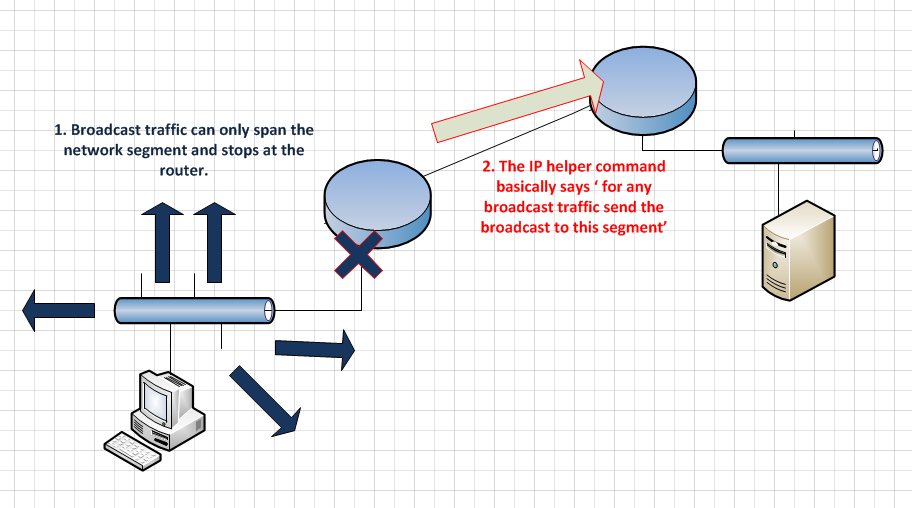
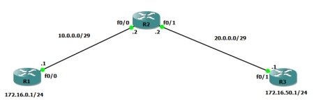
Here is a topology diagram which shows a basis for what we just set up:

201113_IPSEC_1

Show Commands for Cisco IPSEC

The main show command is to check to see Phase 1 is up, this can be done by the command:

Router# sh crypto isakmp sa

201113_IPSEC_2

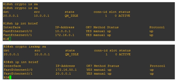
Above is the same command on both routers, here we would expect to see different source and destinations, but they are both the same! This is because the source is always going to be the IP that initiated the tunnel (brought the tunnel up). So for example: on R3 router the source for the isakmp is 10.0.0.1, even though the interface for that router is 20.0.0.1 this is because the the tunnel was brought up by the R1 router, so the source will always be the R1 router. If the tunnel was brought up by R3 then the source and destination will be the other way round on both routers.

Note: – Also worth noting the states QM_IDLE and status ACTIVE are good. This is basically meaning that the ISAKMP SA is authenticated and can be used for subsequent Quick Mode (Phase 2) exchanges.  When you delete a state you will see MM_NO_STATE  and  ACTIVE (deleted) – You may still be able to ping across the tunnel even if this is the state. This is because we would need to wait till Phase 2 goes down (either via no traffic or DPD notification).  

Phase 1’s duty was to bring the table up, and as that was done successfully bringing the tunnel down may not always stop connectivity.

Another show command used to verify  is

Router#sh crypto map

201113_IPSEC_3

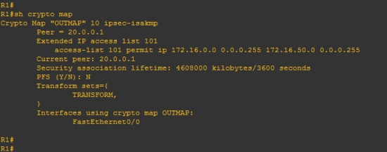
This allows us to see a lot of information about how everything is linked when traffic goes over the tunnel (i.e what map is used, what acl is used, what interface it goes out from etc…) It is also useful as it will tell us if something is missing. The above crypto map is fine, so we see no message but if there is an issue we may see a message like this: WARNING: This crypto map is in an incomplete state! (missing peer or access-list definitions)

Router#sh crypto isakmp policy

201113_IPSEC_4

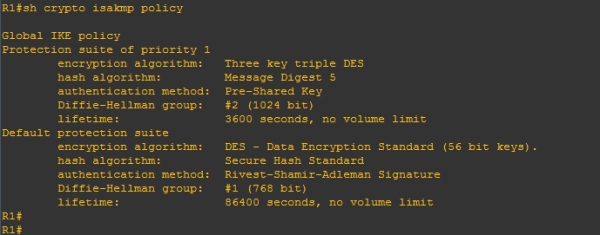
Shows details specifically about the phase 1, this is useful when phase 1 is not coming up and you need to match the attributes against both sides.

Other commands which are useful:

show crypto ipsec sa – Details and informaion about phase 2.
show run and show run all – The show run all command shows all the default settings which are not really shown in a simple show run.

You must remember to verify ACLs are OK and also that static routes are set up if needed.

Creating the Tunnel on a Speedtouch/Thomson

As promised, I will show you how the tunnel was created on the Thomson, this tunnel has to be created in expert mode of the device once logged into the GUI.

1. Create the tunnel.

So once in expert mode navigate to VPN>LAN to LAN. On this page you can start entering the details for the phase one. The descriptors are viewed on a different page, this will show you what encryption etc… is being used. However best practice is to just take note of the descriptors and come back to it once completed Phase 1 and Phase 2. Once we have entered details for the Phase 1 (see below), we can start save/apply and then click New connection to this gateway(to start phase 2 details)

Note:- The images will use the same IP address scheme as the R3 router in the above cisco scenario (this is so it is easier to follow).

201113_IPSEC_5

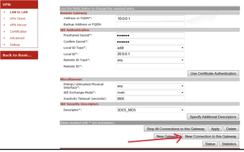
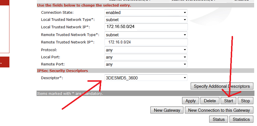
Once phase 1 is added, and you have clicked new connection to this gateway, you can start filling in details for Phase 2.  Fill in the needed details using / notation for the local and remote lan ranges and ensure to select a descriptor (note down the name so it can be verified – shown on next step).

201113_IPSEC_6

If you navigate to VPN>Advanced. You can see the desciptors used for both Phase1 and Phase2

Phase 1 is under Peers> Descriptors

Phase 2 is under Connections > Descriptors (the below image shows phase 2 descriptors).

201113_IPSEC_7

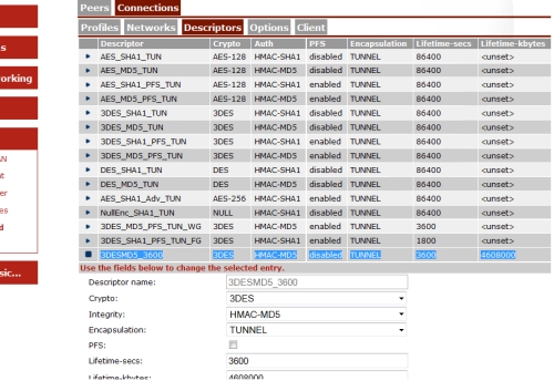
You can verify what settings the device is using by comparing it to the descriptor selected under the phase1/phase2 settings. So for example, on phase 2 we have 3DESMD53600 selected as a descriptor. This tells us that phase2 is using 3des,md5, pfs = disabled,lifetime 3600 etc…

The pre-set templates can be used, or you can create your own custom ones.

2. Configure the Routing

Remember there needs to be a route in place so the traffic knows where to go, on the speedtouch the route has to be more specific and is done from the CLI.

Telnet into the routers cli and add the following command:

ip rtadd dst 172.16.1.0/24 intf=ipsec0 srcintf=LocalNetwork
ip ipconfig addr=172.16.50.1 primary=enabled <<<<<<<< this is routers local IP

Note: – If ICMP does not work you have to ensure the responder is enabled on each interface, go to speedtouch > speedtouch services > icmp eco responder, and then select the interfaces you want icmp to respond on, I.e tunnel and wan and lan etc…

This was the basic process i went through to set up the IPSEC. I did come across some problems, however if you follow the above you should be fine. The next section does details some of the issues i came across.

Problems I came across

When configuring this there were a few problems i came across, some are quite simple however i have detailed them below:

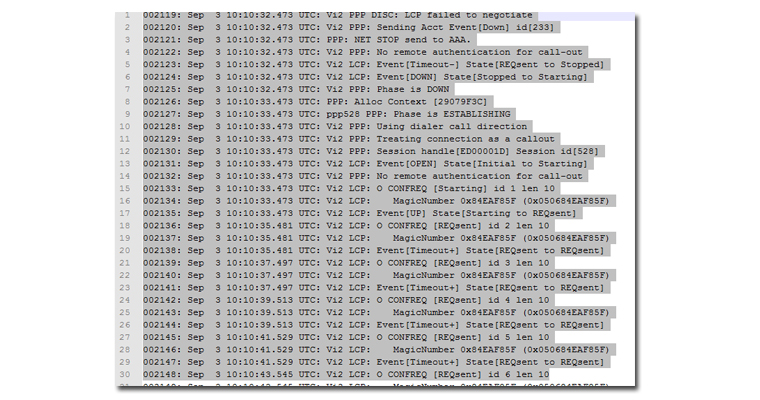
Phase 1 would not come up when initiating traffic from the Cisco, but was fine when bringing the tunnel up from the speedtouch. For diagnosing this i used the speedtouch debug information, and initiated a ping from the cisco.

201113_IPSEC_8

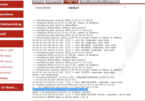
From the debug, i have picked out one specific line ‘attribute unacceptable: unrecognized LIFE_TYPE 2’ – at first i didnt know what this meant but through a lot of testing it is basically telling the following-

The Cisco is sending 2 phase 2 life-types to the Thomson, one for seconds and one for kilobytes. Normally phase 2 will just work with the lifetime in seconds attribute, but for some reason when creating a tunnel between a Cisco and a Thomson both need to be set. In the Thomson i navigated to the descriptors for Phase 2 and created a new descriptor with the kilobytes set exactly the same as the Cisco and use this for the tunnel.

To verify the lifetimes used in the Cisco (as i didnt set they would be using defaults, if they were set they would show in the running config under the crypto map) i did the following:

Router#sh crypto ipsec security-association lifetime
Security association lifetime: 4608000 kilobytes/3600 seconds

After making sure both matched, i sourced a ping from the Cisco and the tunnel came up!

Note: – I did try disabling the kilobyte life-type in the Cisco, however this still did not work for me, so it was easier to just set the attribute in the Thomson.

Another issue i came across was that ICMP was not working over the tunnel, yet the ICMP traffic was clearly hitting the tunnel and brining it up (i could see this in the debugs).

This was a simple fix, yet it was quite confusing. The fix was that there was no route in the speedtouches routing table to the remote connection at the other end of the IPSEC.

I entered the following command in the speedtouch/Thomson CLI and a route for the tunnel was added.

ip rtadd dst 192.168.50.0/24 intf=ipsec0 srcintf=LocalNetwork
ip ipconfig addr=192.168.3.254 primary=enabled

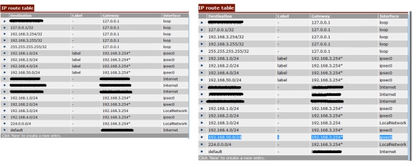
Below shows a before and after screen shot of the IP routing table. As you can see on the before screen shot there is already a route to network 192.168.50.0, but this has a label called label?? im not 100% why this is not enough for the routing table, but after adding that command a new route appears for the 192.168.50.0 network. With this in the table we are able to ping across the tunnel.

201113_IPSEC_9

This post is a basic overview of what i went through when trying to configure the tunnel between a Cisco and Cisco and a Cisco and Thomson/Speedtouch ( apologies for calling the router a Speedtouch one minute and then Thomson the next).


Cisco Auto Install Process – (Preparing Devices for CCE)

Auto-install allows you to connect a new router to the network, turn on the new router, and have it configured automatically from a preexisting configuration file.

Below is the Boot-up sequence of almost all Cisco routers:

1 — Bootstrap program (ROMmon) in ROM runs a POST

2 — Bootstrap then attempts to load IOS from flash to RAM,
2.1 – If no IOS found, it will broadcast for a TFTP server
2.2 – If non found, it will boot minIOS in ROM.

3 — After IOS is found and loaded to RAM,
3.1 – it attempts to load the config file (start-up config).
3.2 – If none

AUTO INSTALL PROCESS.// looking for TFTP

3.3  If fails it goes to set up mode.

Auto Install Process:

As a starting point the router performing the auto install process needs to have no config saved in NVRAM. These devices are normally ordered from cisco as **NO-CONF** it can be done manually by erasing the NVRAM (erase start) and reloading the device.

During the boot up process once the router gets to stage 3.2 (see above) the router does the following:

Step 1: – Routers interfaces cycle for broadcast link – Basically all interfaces will come up one at a time and try and broadcast for a dhcp server. If one interface cant broadcast (nothing connected/no dhcp server reachable), it will put that interface as admin down and then try the next interface.

Step 2: – Broadcast for a DHCP server – Once a successful broadcast is sent out for a DHCP server, the DHCP server responds with an IP address, this can either be a temporary address from a pool or it can be a permanent address that is instructed by the server. The server also responds with an IP address of the TFTP server.

Step 3: – Router connects to TFTP for a network config file – Once the router has an IP address and the TFTP servers address, it will then contact the TFTP server and download a network-config file. This will hold specific info such as the hostname of the device, if it cannot get the hostname from this it will broadcast for a DNS server.

Step 4: – Unicast for Running-config- Once the router has a hostname it will connect with the TFTP server, with its hostname which should marry up with a network config file. This will then be downloaded by the router and stored in running config.

Step 5: – Save running config – The config will be in running config, and needs to be saved. Copy run start will do this.  Note: – If the router originally used a temporary IP (step 2) then this will be sent back to the server using a DHCP RELEASE.

The configuration should now be able to use every time the router boots up as it will be loaded for NVRAM if this is not the case, then remeber you can also delete NVRAM and reload the device to start the process again. If you do start running into problems, It is also worth ensuring the config register is set correctly in the IOS.

Staging Routers.

When using the Auto Install feature, you have to bear in mind that the DHCP server will not always be on the same LAN segment. When this is the case then a ‘Staging Router’ will be used. This is configured with the ‘ IP helper command’:

As a broadcast cannot span past another router, once a it hits a router with the ‘IP helper command’ the helper command will point the broadcast to another segment (ideally this will be the segment that the tftp server is on).

iphelper

800 series routers.

On the newer 800 series routers a special bootstrap has to be placed on the router, which will give it an IP and a direction as to where to look for the TFTP server, by passing the DHCP process.

Additional Info:

http://www.cisco.com/en/US/docs/ios/12_2/configfun/configuration/guide/fcf002.html  — There is alot more usefual information found on this document.

http://www.cisco.com/en/US/prod/collateral/netmgtsw/ps6504/ps4617/data_sheet_c78_598469.html — To check routers that support CCE (cisco configuration engine).

Cisco DSL WICs and Firmwares

Below shows 2 categories in which devices fall into, when connecting over a dsl connection. Either a 800 series router can be used or a DSL WIC card will be used by connection it in another series Cisco router. Note:- There will be other methods of connecting, however my focus is only on these two methods here.

* BT UK ADSL2+ Annex-A using Cisco STM Products [857,867,877,887, HWIC-1-ADSL*] HWIC ADSL modules are based on the ST Micro 20196-PA chipset

* BT UK ADSL2+ Annex-A using Cisco BRCM Products [887-VA and EHWIC-VA-DSL-A] EHWICs support multimode ADSL2/ADSL2+/VDSL technologies based on the Broadcom chipset. The Cisco 880VA Series Multimode VDSL2/ADSL2+ platforms are based on the same Broadcom chipset and support the same DSL modem firmware.

Since IOS 12.4(3)T,  ADSL firmware has been separated into an additional.bin microcode update. The IOS versions do have embedded firmware, however the standalone firmware is preferred for almost all connections.

For 857,867,877,887, HWIC-1-ADSL* (which use ST Micro 20196-PA chipset):

To upgrade the firmware a dsl firmware file needs to be downloaded and renamed as “adsl_alc_20190.bin”. It can then be uploaded to flash (TFTP/SCP shown later in post.)

  1. Download Firmware from – http://software.cisco.com/download/navigator.html       Branch routers>800 Series>(pick a router from the above list i.e. 857)>ADSL Firmware
  2.  Copy Firmware to Flash and ensure the name is “adsl_alc_20190.bin
  3. Reboot the device for firmware to take effect.
  4. “#show dsl interface atm 0” – Should show the firmware source as external rather then embedded!

120913_DSLfirmware_1

The two main fields to be concerned with here are FW Source and FW version (The naming convention of the firmware is also displayed above these).We can verify the firmware has been applied as the FW Source = external
If this read embedded it would still be using the embedded firmware, and there was an error in it using the installed firmware (one thing to check in this scenario is ensuring the file is named adsl_alc_20190.bin)

The below image shows the outcome of a show flash command:

120913_DSLfirmware_2

Here you can verify the naming convention of the file, also notice that although the #show dsl interface atm 0 or  0/0/0 shows the firmware name as different to the file name, (((Investigate issue))))

For 887-VA and EHWIC-VA-DSL-A (supporting multimode ADSL2/ADSL2+/VDSL technologies based on the Broadcom chipset):

  1.  Download firmware from – http://software.cisco.com/download/navigator.html                           Branch routers>800 Series> (select the router i.e Cisco 887VA Integrated Services Router) > Select Very High Bitrate DSL (VDSL) Firmware
  2. Copy the firmware to flash
  3. Configure the router to load from specified location (done under vdsl controller interface) Router(config)#controller vdsl 0
    Router(config-controller)#firmware filename flash:vdsl.bin.bdslfw
    Router(config-controller)#modem UKfeature under controller vdsl 0     (may not tab and must be typed in exact) 
  4. Restart controller by shut/no shutting the controller
  5. Verify by – Router#show controller vdsl 0

120913_DSLfirmware_3

As you can see here the source is user config, this show it is using the firmware we sent to the routers flash and reference under the controller in running config. a show flash command will verify the file name. Also bear in mind, that when using this process, the vdsl controller can be rebooted rather then the entire device.

Useful Links:

During the process of check compatibility with WICs and BT DSLAMs the following sites were ones i found useful and used for reference:


Intermittent DSL and PPP Negotiation diags.

After a ongoing issue with an intermittent dsl connection, and the circuit provider not finding any issues with physical cabling part of the diagnostics i took was to ‘debug ppp negotiation’ and see what i could find.

The output of the negotiation is show below, This was extracted in notepad ++.

080913_PPPtimeouts_1

From the debug we could see that LCP was timing-out. Notice that all the CONFREQ are outgoing messages (O), none are incoming so we are getting no response from the other end. Another a way of showing this is the constant increment on the message ID. we are getting no responses.

Now if attributes were incorrect we would be getting at least a response to tell us they are CONFNAK or CONFREJ but as a result of this we need to look in other areas which could also effect LCP, such as:

* VCI/VPI settings ?
* AAL5MUX or AAL5SNAP ?
* PPPoA or PPPoE ?

CommandS which can verify this are ‘show run’ and ‘show atm pvc’

080913_PPPtimeouts_2

After a bit of reading i found out that the preffered encapsulation for this circuit was AAL5MUX (this will not always be the case). The CCE device used to configure teh connection was defaulting to AAL5SNAP. This had to then be manually changed.

To manually change the encapsulation i typed the following commands.

 (config)#interface atm 0/0/0
 (config-if)#pvc 0/38
 (config-if-atm-vc)#encapsulation aal5mux ppp dialer

After changing this and then shutting down the correct interfaces. The connection came back up and remained stable.

GNS3 CCP encountered problems

GNS was a brilliant substitute from packet tracer for me. It didn’t have the restricted IOS commands and really did allow me to learn a lot more.

The usual stuff is all over the internet (idle PC/hyper-visors etc..) My first real problem with CCP was getting its not loading and once i resolved this there was an issue with half a screen picture only. Here i’ll show how to corrected this and also how to get your GNS communicating with your PC (as CCP is ran on your machine) or VM machine which also was needed during CCNA security study.

These were the issue’s i came across:

* CCP stuck at Retrieving Port

210813_GNS_1

* Not getting full Screen on CCP

210813_GNS_2

The fixes for these were quite simple, all we need to do is ensure we run as administrator and ensure IE is running in compatibility mode.

To run as administrator we just right click and select run as administrator.

210813_GNS_4
The second issue is a problem with IE and compatibility mode, to resolve this all we need to do is set IE to run in compatibility mode. Go to Internet Explorer then click tools>compatibility view settings and either tick the box ‘display all websites in compatibility mode‘ (you can also add 127.0.0.1 to the allowed sites, but its just easier to tick a box and it may also solve future issues you come across). Compatibility view is really designed for older browsers, but not many of us use the really old ones these days.

CCP should now be up and running. However we also now need to ensure GNS3 can talk to it and this is where we have to set up a new loopback adapter in our machine, and connect it to a router in GNS.

To do this we must use the Add new Hardware Wizard. Click Start>Search and type hddwiz.exe and enter. Once the wizard runs click next choosing Install hardware Manually > Network Adapters > Manufacturer = Microsoft and Network Adapter = Microsoft loopback > Next to install and finish.

The you need to locate this loopback adapter (Network and sharing centre) and configure it an IP. Make sure the IP is in the same subnet as the router interface in GNS that your are connecting to the loopback (so example 172.16.0.1/30 router and 172.16.0.2/30 loopback).

If you have a Virtual Machine you want to configure and run CCP on that, then a network adapter needs to be created for the VM and the IP address details configured on that new adapter.

I use Oracle for my Virtual machines (they should come with a ready Virtual adapters, but just in case to add one in oracle VM click on File > Preferences > Network > Add host only adapter. (Ensure that if you are doing it this way that your VM amchine is set up as host only adapter and not NAT in the network settings)

Below is an example

210813_GNS_5

Once we are happy with the adapter and given it an IP address we need to dive into GNS configure a router. Drag a cloud into the topology (representing the interface) select the adapter in the cloud settings (see below). Then connect it up.

Below is an example of the router configuration, ensure in that ip http secure-server, a username, local authentication and ssh is set.

username dan privilege 15 secret dan1234
interface FastEthernet0/0
ip address 172.16.0.1 255.255.255.252
duplex auto
speed auto
ip http authentication local
ip http secure-server
line vty 0 4
login local
transport input ssh

This shows the adapter. If the adapter is not visible you may need to reboot your machine. I have no idea why but this has happened to me a few times.

210813_GNS_6

And that’s it now you should be able to use CCP. The latter adding a interface in GNS is quite useful, especially if you want a server running on a VM and want it connecting to your network.

Also i appreciate this post maybe a little long and dumb’d down in certain areas, im new to this so please be patient. If some of the above information is incorrect please let me know and if true i’ll gladly correct,

Thanks.

PPP Negotiation Process.

PPP is a Data-link communication protocol In order for it to successfully complete it must go through certain phases. There are 3 main components/steps to PPP and its negotiation process:

Step 1: – LCP (Link establishment Phase).
* This is where parameters are specified for th link o be established, both devices need to agree on authentication type, compression, error detection, multilink and ppp callback. Once the values are agreed it can move onto step 2 or 3.

Step 2: – Authentication (PAP,CHAP or EAP).
* This is an optional phase, but if implemented both devices need to know that the device they are speaking to is who they say they are.

Step 3: – NCP ((Network Control Phase).
* This is the laye 2 to layer 3 transition phase. It provides communication with the IP layer (IPCP). Gives us an IP address we can then communicate with.

One way of verifying step 1 is to run a “sh int atm 0/0/0” (will show the lcp status)

080913_PPP_1

LCP REQsent

(LCP OPEN = LCP successful, LCP CLOSED = Indicates LCP failure, LCP REQsent = both sides could not match parameters i.e mis match of encapsulation)

During the process of PPP negotiation the different packets we will see are:

1. (CONFREQ) > The values that are sent to complete stage (request for information).
2. (CONFREJ) > This will be a return packet if the request is not acceptable or not recognizable,
3. (CONFNAK) > This will be the return packet when the request is recongnizable, however some of the values are not accepted i.e Chap is sent but the other end wants to authenticate with PAP.
4. (CONFACK) > When the router values are accepted, (response to the CONFREQ).

There are also:

1. (TERMREQ) > This is when there is a request for a LCP closure
2. (TERMACK) > This is acceptance of the above.
3. (ECHO REQ/REPLY) >- The PPP keep alives for the connection.

Below shows an overview of the process.

080913_PPP_2

DEBUG PPP Negotiation:

The debug PPP negotiation command is useful because it can not only be used as a vital diagnostic tool, but it also shows the full PPP negotiation process.

Below is an extract from a live debug. You can see the router goes through the 3 phases needed for successful PPP negotiation. Now not all PPP negotiation will go through the exact same process, but it still will be quite similar. (i.e. in a scenario where there is no authentication – as this is an optional phase).

The following images shows how to read a debug output.

080913_PPP_3

Below is the extract of the different phases as seen in a debug output.

080913_PPP_4

Here you can see the LCP start. Notices the stage field changes from PPP (global stage) to LCP. The first CONFREQ is an outgoing request with an ID of 1. However it is followed by an incoming request (ID 124), requests specific LCP attributes (CHAP authentication, MRU, Magic number). The router automatically responds to request which is a CONFACK with its matching attributes. Notice that the response has the same ID number. This way we can match the incoming and corresponding outgoing message.

080913_PPP_5

Once both connections have agreed on LCP details they then need to authenticate against one another. In this output you can see that an Incoming challenge is sent from the remote device, This router has responded to the challenge but full authentication has been unsuccessful. We see this sometimes when authentication has to go through multiple hops. Although the response if a fail here, and the lcp establishment needs to start again (always restarts if there is a fail), the next time the router gets to this stage it will bypass this hop “bras-red4.mqd” (or teh bras will just let it through) and the authentication will go straight to the next stage.

080913_PPP_6

This is the last stage on PPP and it is the NCP stage, so that layer 2 can communicate with layer 3. Notice again the change of stage, which now reads ‘IPCP’. It also shows that LCP stage is complete. The key here is the issuing of the gateway IP (the address the IP needs to speak to, to get its credentials) and teh confirmation of this IP. See ID 87. Once the CONFACK is sent. The router now knows it needs to speak to this IP address to progress.